What is Computer Architecture?
Computer architecture is the design and organization of a computer’s core components and systems, defining how it processes instructions and manages data.

About x86 Toolchain
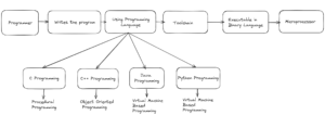
The following concept of a toolchain is applicable to the C and C++ programming languages:
- The primary function of a toolchain is to convert a program from a human-readable format into a machine-readable binary format.
- The toolchain concept is applicable to every programming language.
- All the tools in the toolchain are used in a chained format, where the output of one tool serves as the input to the next tool.
- The output of the final tool in the chain is the executable file.
- Once we obtain the executable file, we can load it into the microprocessor for execution.
- The following points about the toolchain are common to both C and C++ programming.
- Both of these languages are high-level, native programming languages.
- A native programming language interacts directly with the microprocessor.
Step 1
- Write the program using an editor.
- Save the file with the extension .c.
- Name the file, for example, hello.c.
Step 2
- Pass the file to the compiler.
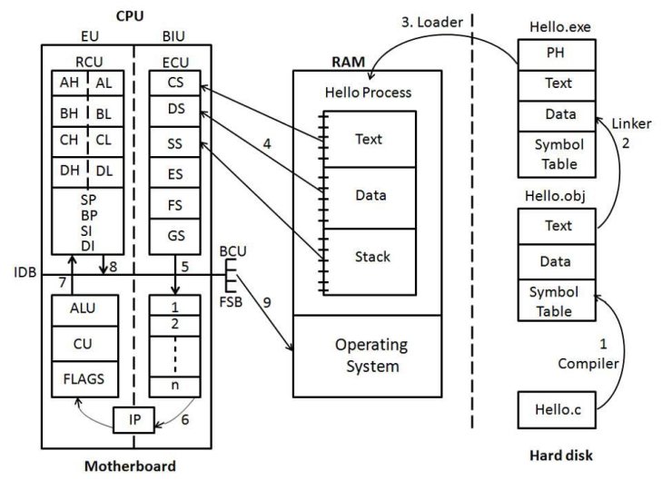
- In this context, the compiler internally includes the preprocessor, compiler, and assembler.
- The output of the compiler is an .obj file in binary format.
- The .obj file is divided into three sections:
- Text – Contains the compiled instructions of the program in binary format.
- Data – Contains memory for global variables used in the program.
- Symbol Table – A table containing information about the symbols (variables) used in the program.
Step 3
- Pass the .obj file to the linker.
- The linker links our .obj file with other dependent .obj files.
- The linker creates an .exe file, which is the executable file.
Step 4
- The executable file created by the linker is stored on the hard disk.
- To execute the file, it must be loaded into RAM.
- The loader is responsible for loading the executable file into RAM.
Step 5
- The primary header is added to the .exe file.
- The primary header contains information about the executable file.
Step 6
- When the loader loads the file into RAM, it is considered a process.
- The process loaded into RAM is divided into three parts: Text, Data, and Stack.
- Stack: Contains information about the functions written in the program.
Step 7
- The process is now loaded into RAM and divided into Text, Data, and Stack sections.
- RAM is not responsible for executing the process; the process is passed to the microprocessor.
Step 8
- The microprocessor has limited memory compared to RAM, so direct loading of text, data, and stack is not practical. Therefore, each section is divided into multiple segments.
- The Text segment is copied into CS (Code Segment).
- The Data segment is copied into DS (Data Segment).
- The Stack segment is copied into SS (Stack Segment).
- If these segments are full, the ES (Extra Segment) is used.
- If the ES is also full, FS and GS are used (FS and GS do not have specific full forms).
Step 9
- Data from the segments is copied into the instruction queue.
- The instruction queue fetches one instruction at a time and forwards it for execution.
- The IP (Instruction Pointer) fetches one instruction at a time.
Step 10
- The instruction is forwarded to the ALU (Arithmetic Logic Unit) if it relates to an arithmetic operation; otherwise, it is forwarded to the CU (Control Unit).
- The FLAGS register indicates the internal status of the microprocessor.
Step 11
- The instruction is stored in the CPU registers.
- There are multiple CPU registers, each serving a specific purpose:
- AH, AL – Arithmetic / Accumulator Register
- BH, BL – Base Register
- CH, CL – Count Register
- DH, DL – Data Register
- SP – Stack Pointer
- BP – Base Pointer
- SI – Source Index
- DI – Destination Index
- The instruction is executed within these CPU registers.
Step 12
- The output of the instruction is forwarded to the operating system via the IDB (Internal Data Bus).
- The operating system displays the result on the screen.
Important Abbreviations and Full Forms
.obj – Object Code
.exe – Executable
PH – Primary Header
RAM – Random Access Memory
BIU – Bus Interface Unit
ECU – Execution Control Unit
IP – Instruction Pointer
RCU – Register Control Unit
EU – Execution Unit
BCU – Bus Control Unit
FSB – Front Side Bus


